10+ data entity diagram
Student Score - Ternary Relationship. Relationship name will be written inside them.
How Do You Draw A Visual Paradigm Entity Relationship Diagram
The entity relationship model ERM is a computational model that describes the knowledge shape of a difficulty domain in terms of system and connections.

. Thus the computational form of a problem domain being modelled is expressed by an ERD. Click File Data Modeler Print Diagram To Image File. An Entity Relationship ER Diagram is a type of flowchart that illustrates how entities such as people objects or concepts relate to each other within a system.
Now Its time to translate the entities relationships. Click the New Entity icon. Here is an example displaying the number of people migrating from one country to another.
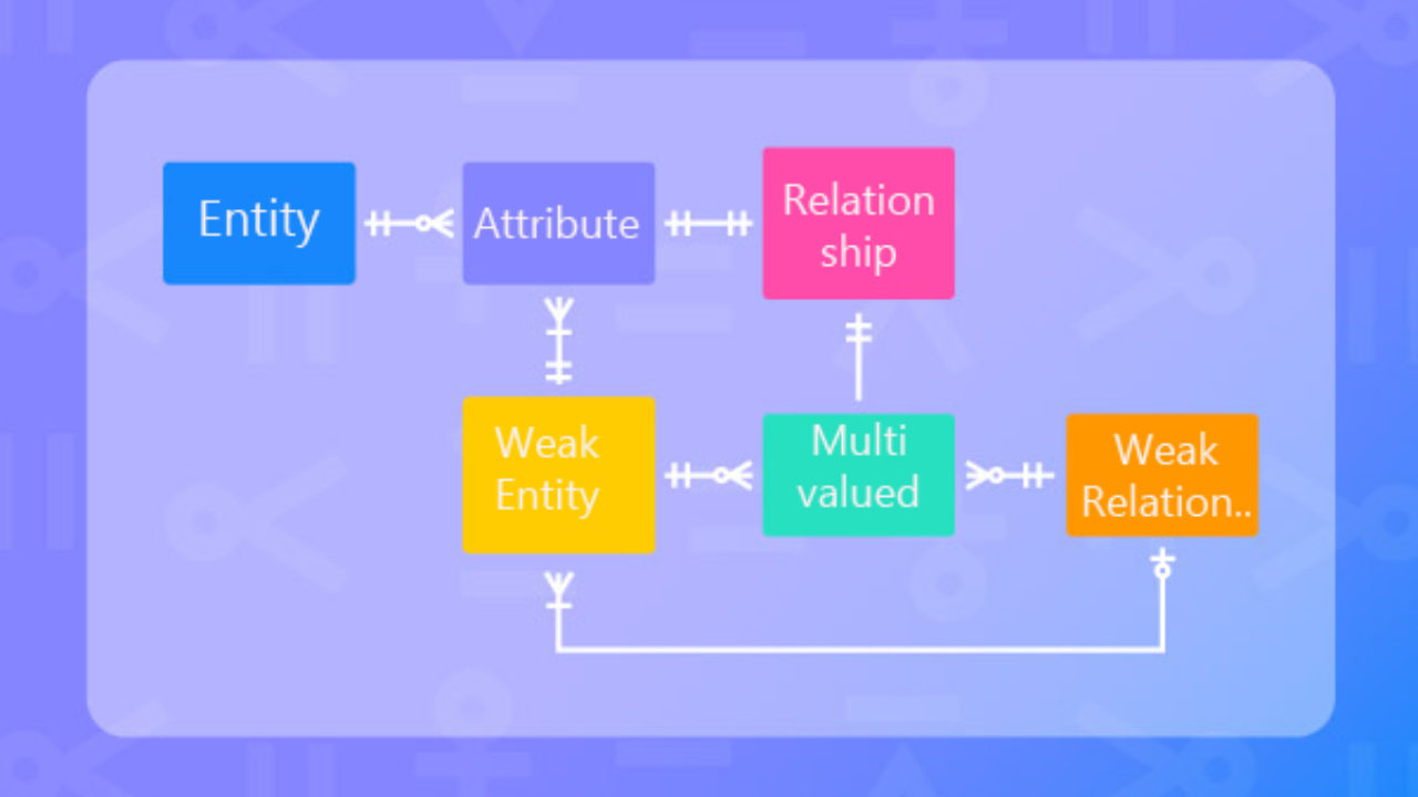
An entity in set B can be associated with at most one entity in set A. Entity Relationship Diagram DrugsFDA consists of 11 tables. A diamond shape is used to show the relationship between the entitiesA mapping with weak entity is shown using double diamond.
One course can be enrolled by at most one student. Check one or more schema names. Although many solutions were.
ERDPlus is a database modeling tool to quickly and easily create Entity Relationship Diagrams Relational Schemas and Star. Storageimplementation details Algorithmically. The ERD is displayed.
Works with most contemporary RDBMS tools including Oracle MySQL Microsoft SQL Server PostgresSQL Teradata IBM DB2 Microsoft Access and others. The size of the arc is proportional to the importance of the flow. A process is a program which is currently in execution.
Create the Books entity as follows. There are standard data flow diagram symbols used to represent different parts of the system. Data flow diagrams are intended for graphical representation of data flows in the information system and for analysis of data processing during the structural projection.
Although data modeling has become a necessity around 1970s there was no standard way to model databases or business processes. An entity is a thing person or. In such a scenario using Entity framework may result in a slow performance because we need to process by selecting data from a table then run some loops from other tables.
The Books entity describes each book in the library. An entity set is a collection of entities of an entity type at a particular point of time. Point of Sales POS System.
ER Diagrams are most often used to design or debug relational databases in the fields of software engineering business information systems education and research. There are several situations where your applications may need to display data by combining two or more tables sometimes even more than 7-8 tables. It was developed to reflect more precisely the properties and constraints that are found in more complex databases such as in.
Data flow diagram often used. Specific operations based on the data can be represented by a. In this article we are going to discuss about process process state diagram and process control block PCB.
Entity-relationship modeling or ER Diagram symbols are part of a conceptual approach to design that models objects as abstract data types and the relations between these objects as predicates. What is an ER diagram. The enhanced entityrelationship EER model or extended entityrelationship model in computer science is a high-level or conceptual data model incorporating extensions to the original entityrelationship ER model used in the design of databases.
Entity types relationships and constraints Sanity check of data functional requirements Reference for unitintegration testinganalysis ConciseHigh-level Easy to understand technically Easy to communicate with non-technical users Facilitates focus on data vs. Also it works with data engines. Attribute-refers to the unique characteristic or property of an entity.
ActionTypes_Lookup ActionTypes_LookupID int IDENTITY11 NOT NULL ActionTypes_LookupDescription varchar100 NOT NULL. Using the entity relationship diagram to sketch your database is a common way to visualize your tables columns and their relationship. Select a DB connection add one if none.
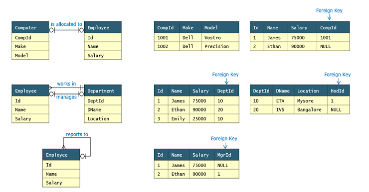
Customer Journey Mapping 18 See All Basic Customer Journey Map Template. The ER Diagram show the relationship between entities tables and the primary key-foreign key relationships between the tables relationships. A data-flow diagram is a way of representing a flow of data through a process or a system usually an information systemThe DFD also provides information about the outputs and inputs of each entity and the process itself.
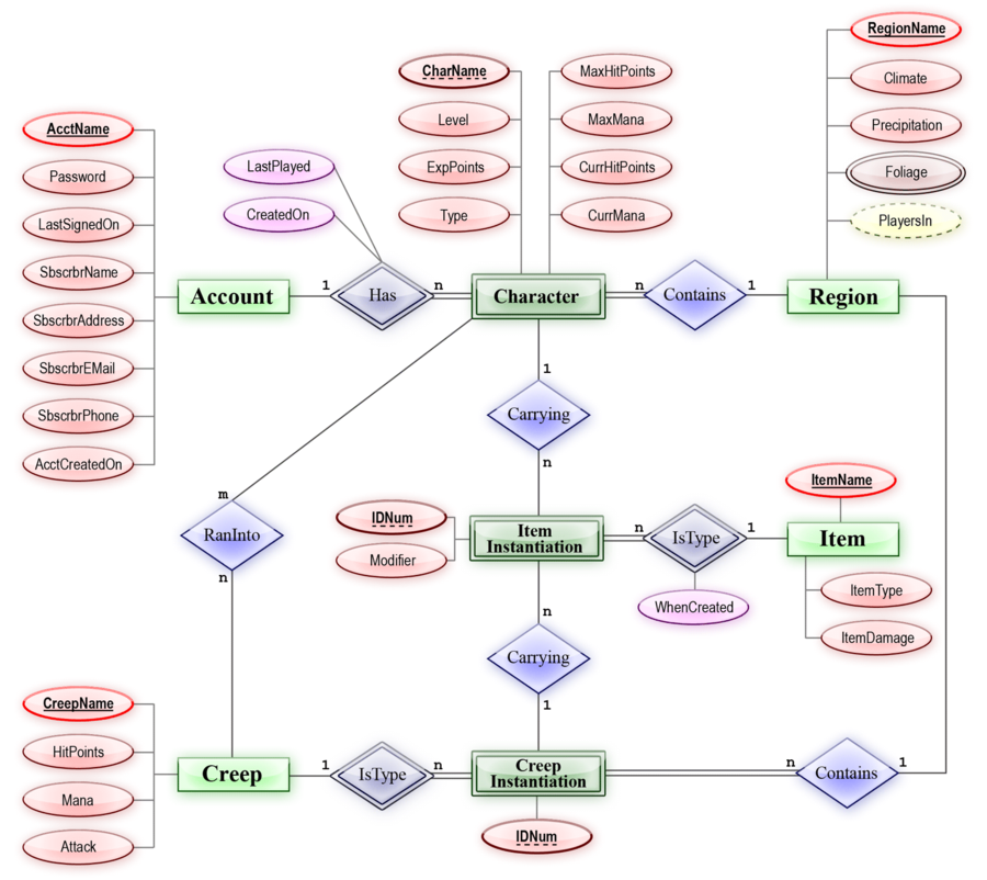
Select from common data types and data sizes. Entity Framework solves problems in entity models relationships and business logic. Symbol Used- Example- Consider the following ER diagram- Here One student can enroll in any number zero or more of courses.
A chord diagram represents flows or connections between several entities called nodesEach entity is represented by a fragment on the outer part of the circular layoutThen arcs are drawn between each entities. Entity Framework is the development of data-oriented applications using ADONET. Another term to know is entity type which defines a collection of similar entities.
Export the diagram as follows. Data flow diagram DFD is the part of the SSADM method Structured Systems Analysis and Design Methodology intended for analysis and information systems projection. In an entity relationship diagram ERD an entity type is represented by a name in a box.
This is usually represented by rectangles. Different developers use different notation to represent the cardinality of the relationshipNot only for cardinality but for other objects in ER. For example in Figure 81 the entity type is EMPLOYEE.
Entity-this represents the name of an object person thing event or place where data is stored. Weak Entity-unlike a strong entity that is defined by its attributes a weak entity solely depends on the existence of another entity. A program by itself is not a process but it is a passive entity just like content of a file stored on disk while a process is an active entity.
An Entity Relationship Diagram ERD is a visual representation of different entities within a system and how they relate to each other. Check one or more objects to import. And in the Logical pane press diagonally drag and release the mouse button to draw an entity box.
Click in the logical model pane in the main area. For example youll use one shape to represent an external entity and another symbol for a process. This vastly speeds.
Here are the symbols youll need to use to create a DFD. A data-flow diagram has no control flow there are no decision rules and no loops. To learn more about data flow diagram symbols check out our guide here.
In the main area right side of the Data Modeler window click the Logical tab. As an object interaction diagram ERD the consequence of modelling using the ERM is graphically depicted. An entity in set A can be associated with any number zero or more of entities in set B.
Click File Data Modeler Import Data Dictionary.

What Is An Er Diagram And How To Implement It Edureka

39 Handy Info Ideas Relationship Diagram Database Design Diagram Design

Local Area Network Lan Computer And Network Examples Software Diagram Examples And Templates Personal Area Pan Networks Computer And Network Examples Example Of Diagram
What Is The Importance Of An Entity Relationship Diagram Quora

Local Area Network Lan Computer And Network Examples Software Diagram Examples And Templates Personal Area Pan Networks Computer And Network Examples Example Of Diagram

Free 7 Sample Relationship Diagram In Pdf Ms Word
What Is An Er Diagram And How To Implement It Edureka

Dbms Case Study Dbms Erd Management Information Systems

10 Erd I E Entity Relationship Diagrams Interview Q As Java Big Data Career Companion

Logical Database Design Of The Triple Table And Er Diagram Showing Download Scientific Diagram
What Is The Importance Of An Entity Relationship Diagram Quora
Entity Relationship Model Wikiwand
Data Modeling Using Sql Developer Data Modeler Spheregen

Introduction To Er Diagram Model Knoldus Blogs
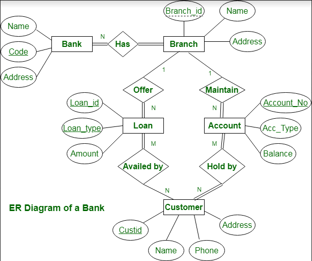
Er Diagram Of Bank Management System Geeksforgeeks
Free 7 Sample Relationship Diagram In Pdf Ms Word

Er Diagram Of The Current Common Iq Meta Model Entities Boxes With Download Scientific Diagram